Jump to content
Sign in to follow this  
BsEMS

FI SP4 Enclosure w/ DWG

Recommended Posts

Im going to try and be brief.. since I'm at work. (One of the very few sites I have access to!)

I used WinISD to play with output numbers. Of those, I valued port velocity::frequency ratio. And I tried to configure a flat response bandwidth while keeping my desired tuniing @ 29hz.

Quick specs:

1. Its a trunk build ( 4 door camry)

2. substage amp VFL 150.1

3. Rear firing design // 15" SP4 with electrical to boot. 306A - 274A alt (Hot). 306A Peak (cold) . 178A Hot @ idle

I can post more details on Port volume later, I left the last dimension of port length at home. But what your seeing is port depth 17.25, height 15.5, length is somewhere between 26.xx to 28.xx. I cant remember off top. What has been changed though is the front wall 2nd baffle will be extended to the left to eliminate that 1" gap between it and the interior port wall. And also will be changed the front enclosure wall will be cut to extend over the right side wall and left slot wall. So when I fasten the walls the screws will sit parallel with the subs linear force, not coming in from the sides of the enclosure walls.

I dont think I'll need any bracing. With the 2900 watts...and not a large sized box with the slot port acting as bracing all I will do really is glass the kerfs. And if I want overkill Ill reinforce corners with more GRP. All thats left for me to do is build a prototype enclosure from cardboard and make sure she fits through the opening of the trunk. And possibly make the radius of the inner port wall larger to make it less of a degree turn to create a smoother flow of air.

If you dont like my dwg.. tell me, I dont care lol. Im open for any and all input. Thats how we learn isn't it. Whether you have 1 post or 100000 posts.. im game for listening to opinions.

subbox1.png

Edited by BsEMS

Share this post


Link to post
Share on other sites

Drawing looks nice.

I would go ahead and extend the baffle all the way across.

Also I would still add bracing. Dowel rod would be fine.

Share this post


Link to post
Share on other sites

There would be more of a benefit to kerf the port opening than where you have it now.

Share this post


Link to post
Share on other sites

What year Camry? if It's the same style as mine, 2003, you might want to mock up a box and make sure it'll fit into the trunk. 34wx17hx24d is the outside dim of my 15" box and clears. My dual 12" box is 38x15x20 and that extra width makes it a tight fit into the opening.

th_IMG_20120317_173757.jpg


I have a 15" sp4 that I swap around with a pair of 12" Sundowns, keep going back and forth. Like the 12"s because I can fire both and port forward and not have to deal with any rattles. Have it temporarily sealed off right now and sounds decent. I've got a pair of n2's to go in that box when/if i get more amp. The 15" sp4 and the pair of sundown sa12s both meter about the same peak, but the sp4 is louder lower.


My Sp4 is in about 4.7 cubes net tuned to 31 with an 8" aero. Sub back, port driver side. On a Sundown 3k. It gets down pretty good. Wish the back seat opening was about 4" taller, I'd do 15" sp4 sub&port forward. I've tried sub forward, port pass and it wasn't as good as sub back.

Share this post


Link to post
Share on other sites


There would be more of a benefit to kerf the port opening than where you have it now.


How is this so? I assume kerfing the inner port wall (opening) would kind of act in a expanding wave type deal. But if only at the edge..how would an inch or so distance of port opening kerf be more effective than kerfing the entire inner wall(s) of the port?

My goal with kerfing is to create a more efficient path for air to travel, increasing port air velocity and lessening resistance from the traditional 90degree L-Port design.

Share this post


Link to post
Share on other sites

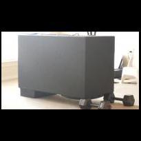
I've already built a mock-up. And the only adjustment I made was having total height at 16.75 instead of 17. And it fit like a muthfreakin glove. 40" wide fits just perfect into the trunk opening. I bought some cheap 3/4 cello foam from Home Depot, got a straight edge + a retractible blade. And cut, taped it to perfection. It turned out to be a solid representation of my enclsure... all dimensions falling within 1/16 to 2/16 tolerance (due to the density of the foam board and the cleanliness of the cuts)

CameraZOOM-20130501234357212.jpg

Edited by BsEMS

Share this post


Link to post
Share on other sites


Drawing looks nice.

I would go ahead and extend the baffle all the way across.

Also I would still add bracing. Dowel rod would be fine.


I seriously considered dowel rods.. but only b/c i see a lot of builds with them. But if I take into account the largest "empty" space of my box w/o bracing is going to be around 33 x 12 inches of area. Theres no way that small space will need extra support, especially if the sub isnt going to be mounted on top the box.

Share this post


Link to post
Share on other sites


There would be more of a benefit to kerf the port opening than where you have it now.


How is this so? I assume kerfing the inner port wall (opening) would kind of act in a expanding wave type deal. But if only at the edge..how would an inch or so distance of port opening kerf be more effective than kerfing the entire inner wall(s) of the port?

My goal with kerfing is to create a more efficient path for air to travel, increasing port air velocity and lessening resistance from the traditional 90degree L-Port design.


I am not an engineer in fluid mechanics but I would think it would be more beneficial to decrease turbulence at the mouth of the port. Any bends throughout the port length are typically cut at a forty five degree angle to reduce turbulence. Which is standard practice for many speaker enclosure designers. What is most important is that your port is properly designed for your enclosure.

Share this post


Link to post
Share on other sites


There would be more of a benefit to kerf the port opening than where you have it now.


How is this so? I assume kerfing the inner port wall (opening) would kind of act in a expanding wave type deal. But if only at the edge..how would an inch or so distance of port opening kerf be more effective than kerfing the entire inner wall(s) of the port?

My goal with kerfing is to create a more efficient path for air to travel, increasing port air velocity and lessening resistance from the traditional 90degree L-Port design.


I am not an engineer in fluid mechanics but I would think it would be more beneficial to decrease turbulence at the mouth of the port. Any bends throughout the port length are typically cut at a forty five degree angle to reduce turbulence. Which is standard practice for many speaker enclosure designers. What is most important is that your port is properly designed for your enclosure.


Is there legitimate turbulence at the mouth though? I dont know. I assumed since it is coming from a confined space into an open space that turbulence(resistance to flow?) would be minimal at the mouth. But yes, I did try to calculate port volume as accurately as possible for my setup.

Share this post


Link to post
Share on other sites

Minor change- I will tune a bit higher @ 32-33 hz. Doing this should gain overall output and lose very little low end.

Share this post


Link to post
Share on other sites


There would be more of a benefit to kerf the port opening than where you have it now.


How is this so? I assume kerfing the inner port wall (opening) would kind of act in a expanding wave type deal. But if only at the edge..how would an inch or so distance of port opening kerf be more effective than kerfing the entire inner wall(s) of the port?

My goal with kerfing is to create a more efficient path for air to travel, increasing port air velocity and lessening resistance from the traditional 90degree L-Port design.


I am not an engineer in fluid mechanics but I would think it would be more beneficial to decrease turbulence at the mouth of the port. Any bends throughout the port length are typically cut at a forty five degree angle to reduce turbulence. Which is standard practice for many speaker enclosure designers. What is most important is that your port is properly designed for your enclosure.


Is there legitimate turbulence at the mouth though? I dont know. I assumed since it is coming from a confined space into an open space that turbulence(resistance to flow?) would be minimal at the mouth. But yes, I did try to calculate port volume as accurately as possible for my setup.

This excerpt explains port turbulence at the mouth of the port http://books.google.com/books?id=Twu0oHE1ukgC&pg=PA82&lpg=PA82&dq=subwoofer+port+turbulence&source=bl&ots=CmScq2T7PB&sig=54zGZg59cPG50S2PMbFg_OJh0vU&hl=en&sa=X&ei=bziKUZHiJ4_e4AOSq4GAAQ&ved=0CEIQ6AEwBg

Share this post


Link to post
Share on other sites

I'd love to sit and read all of that. But cant right now. What chapter or page references what we're discussing?

Share this post


Link to post
Share on other sites

I'd love to sit and read all of that. But cant right now. What chapter or page references what we're discussing?

I guess a single page pulled from a book with a couple pictures is a lot to read these days.

If you clicked on the link you would see a page refrenced lol

Share this post


Link to post
Share on other sites

That is a good book there, might be worth your time to read.

Share this post


Link to post
Share on other sites


I'd love to sit and read all of that. But cant right now. What chapter or page references what we're discussing?

I guess a single page pulled from a book with a couple pictures is a lot to read these days.

If you clicked on the link you would see a page refrenced lol


LOL. man when I clicked the link it took me straight to the cover page. And yes..there was two pictures on it! B-)

Share this post


Link to post
Share on other sites


I'd love to sit and read all of that. But cant right now. What chapter or page references what we're discussing?

I guess a single page pulled from a book with a couple pictures is a lot to read these days.

If you clicked on the link you would see a page refrenced lol


LOL. man when I clicked the link it took me straight to the cover page. And yes..there was two pictures on it! B-)


You're using Internet Exploder aren't you?  lol


Pages 82 & 83 are the pertinent information they're referencing, but just for future reference that's a book everyone in this hobby should own for their own referencing.  7th edition is the latest, just FYI.

Share this post


Link to post
Share on other sites

I got it to work.  Must have been the jobs' computer internet limitations. 

Share this post


Link to post
Share on other sites
Sign in to follow this  

×