Leaderboard
-
SQLMonte
Members16Points146Posts -
CadillacMatt
Members3Points681Posts -
Soapbox
Members1Points417Posts -
Tirefryr
Super Moderators1Points30,516Posts


Popular Content
Showing content with the highest reputation on 01/08/2010 in all areas
-
...And why? I usually watch anything informative because I figure if I'm watching the toob I might as well learn a little something while I'm at it...I can never really get into reality shows they just tend to piss me off. And the news is always so depressing it's not worth watching. What about you guys?1 point
-
1 pointDo v-dubs have a similar communication network to gm's class II data bus?1 point
-
1 pointWell said for the most part. This forum is not anti-AQ. Just a little different segment of the market. So the clan here is more into SQ than SPL???1 point
-
1 pointSo do you have to have SSA equipment in your car in order to get on there?1 point
-
I always thought Class D was the way to go as far as sub amps but hearing the comment about Class D here is pretty much the same thing my buddy once told me. He promises never to run a class D amp ever again. Gotta talk to him more to figure out why.1 point
-
1 point
-
1 pointYou guys do realize that SPL scores have NO correlation to how loud a system will be listening to music correct? This thread and question is pointless, as are all threads of this nature.1 point
-
1 point
-
1 point
-
1 pointThe only Vibe i've ever heard of are the Lanzar line of amps and the magazine1 point
-
1 pointI never really was a fan of Eclipse, as far as looks went. But they had some nice features though1 point
-
1 pointthat sub is causing quite the commotion on various boards. the thing is a beast, no doubt....i just wonder if something has gone afoul cause he's been awfully quiet since the new year1 point
-
What size Xcon are you getting? Can't wait to see how that box turns out1 point
-
1 pointI ditched my rears on my most recent build and surprisingly liked it. But I have a feeling that once I get both of my 2512's put in that i'm gonna have to add another set of comps up front to balance things out.1 point
-
1 point
-
1 pointThanks for the link to the same video interesting, I guess my comp didn't load the page completely. oh well1 point
-
1 pointMajor props to ya, I don't have the balls to even attempt to do a project like that.1 point
-
1 pointAfter all of my reading. I knew I had read most of the pile. But then Jacob pointed me this direction. Thanks. The Aveo and the Fit are in the same sub compact class. No worries. Soapbox1 point
-
Haha I do the SAME thing! I put on a program to watch and then I'll get engrossed in the computer, before I know it the credits are rolling and I miss the entire show...1 point
-
I voted, usually I dont watch tv it is watching me. Im either on the computer or doing something to where it is just background noise, lately I havent had it on since its wasting electricity to do so.1 point
-
So many people watch the food channel, I was going to put that as an option but I could only put 10 choices1 point
-
I grew up on the Discovery Channel, that why I'm such a freaking genius! But I don't watch TV anymore.1 point
-
1 point
-
1 point
-
Comedy(The office, Mighty Boosh, Modern Family) Then just sports and the history channel.1 point
-
I'm a sports guy especially Hockey! Then it's the "Informative" stuff.1 point
-
If this will be your system for now then get a good secondary battery and a volt meter to watch your voltage, wait on the HO Alternator till you need it or if your voltage is still bad.0 points
-
0 pointsIt depends what you will use it for, please provide us with more information. Read new member guidelines before posting again.0 points
-
0 pointsOk I got you, check out these speakers if you want some good midrange speakers. I was gonna get them before I got these horns but decided to go with some horns this route since I have had the 20+ plus speakers in a Saturn Ion, you talking about a nice advertisement vehicle while being in school. Since that is the trend in Florida, I did a good amount of installs because of my setup.0 points
-
0 pointsLow Pass anywhere from 60/80/100 hz depending on what you like and if you have midbass and where they are set at. Play around with the phase to see what you like but some leave it alone. Be sure to set your gain with a DMM, not the best or accurate way unless you can tell signs of stress on a woofer.0 points
-
0 pointswhat do you mean when you say speakers on axis? Like how the earth is on an axis; it means pointed, tilted or aimed in a direction. Duran do you axis them towards the driver, towards the center of the car or drivers speakers toward passenger and vice versa. Thanks.0 points
-
0 pointsTo me its a personal preference and to each its own, just build a sturdy box and follow the tips in my previous post. You will be good put up a build log when you start the install.0 points
-
0 pointsIt sounds like an rca problem or something on the amp may be loose causing it to vibrate more than normal when the subs are running.0 points
-
-1 pointsStephen Mantz on DF http://zedaudiocorp....l-GREYSCALE.pdf Damping Factor – This amplifier specification has been blown out of all proportion. What it means is the ability of the amplifier to resist a change in it’s output voltage. The formula is DF = Speaker Z/Amplifier output Z (where Z is impedance). So many manufacturers have claimed ridiculous, and often false damping factors. A damping factor of 1000 implies that the output impedance of the amplifier is .004ohm (4ohm load). The only way to attain this figure is to apply masses of negative feedback (or use positive feedback) and too much feedback makes amplifiers sound harsh and clinical. Also damping factor changes with frequency. The lower the frequency the higher the DF number. Typically the DF can be ten times larger at higher frequencies. Let us take this amplifier whose output impedance is .004 ohms (Zout). The speaker circuit is a series circuit and the following impedances (resistances) are in series with this .004 ohms. Let us assume that this DF measurement was made at the amplifier’s speaker terminal. The first extra contact resistance is the speaker wire to the speaker terminal (WT ohms). Then there is that of the wire itself for two conductors (W). Next is the contact resistance of the wire to the speaker terminal (WS). Next there is the contact resistance of the wire from the speaker terminal to the voice coil (WV) and lastly there is the DC resistance of the voice coil itself (DCR). So what we have is a series circuit with the following resistances in series and adding up. WT+W+WS+WV+DCR+Zout. WT, W, WS, WV and Zout are very small indeed. Certainly less than .1 ohms. Whoa, look what has happened the EFFECTIVE DAMPING FACTOR has been reduced from 1000 to 40 by just taking into account those pesky unavoidable contact resistances. Now for the cruncher, remember that the DCR is also in series and is typically 3.2 ohms for a nominal 4ohm speaker. So we must add 0.1+3.2 = 3.3 ohms and now EFFECTIVE DAMPING FACTOR is now a magnificent 1.212! (4 divided by 3.3). This is the real world. We see that the DCR of the speaker swamps all other resistances in the speaker circuit and the .004 ohms amplifier output impedance is almost meaningless. It has been found that a DF of about 20 is quite sufficient to dampen the voltage spikes from the speaker. An eye opener this one is it not? Good tube amps sound marvelous – low damping factors!-1 points
-
-1 pointsAudioholics article on DF http://www.audioholi...system-response Much ballyhoo surrounds the concept of "damping factor." It's been suggested that it accounts for the alleged "dramatic differences" in sound between tube and solid state amplifiers. The claim is made (and partially cloaked in some physical reality) that a low source resistance aids in controlling the motion of the cone at resonance and elsewhere, for example: "reducing the output impedance of an amplifier and thereby increasing its damping factor will draw more energy from the loudspeaker driver as it is oscillating under its own inertial power." This is certainly true, to a point. But many of the claims made, especially for the need for triple-digit damping factors, are not based in any reality, be it theoretical, engineering, or acoustical. This same person even suggested: "a damping factor of 5, ..., grossly changes the time/amplitude envelope of bass notes, for instance. ... the note will start sluggishly and continue to increase in volume for a considerable amount of time, perhaps a second and a half." Damping Factor: A Summary What is damping factor? Simply stated, it is the ratio between the nominal load impedance (typically 8W ) and the source impedance of the amplifier. Note that all modern amplifiers (with some extremely rare exceptions) are, essentially, voltage sources, whose output impedance is very low. That means their output voltage is independent, over a wide range, of load impedance. Many manufacturers trumpet their high damping factors (some claim figures in the hundreds or thousands) as a figure of some importance, hinting strongly that those amplifiers with lower damping factors are decidedly inferior as a result. Historically, this started in the late '60's and early '70's with the widespread availability of solid state output stages in amplifiers, where the effects of high plate resistance and output transformer windings traditionally found in tube amplifiers could be avoided. Is damping factor important? Maybe. We'll set out to do an analysis of what effect damping factor has on what most proponents claim is the most significant property: controlling the motion of the speaker where it is at its highest, resonance. The subject of damping factor and its effects on loudspeaker response is not some black art or magic science, or even excessively complex as to prevent its grasp by anyone with a reasonable grasp of high-school level math. It has been exhaustively dealt with by Thiele and Small and many others decades ago. System Q and Damping Factor The definitive measurement of such motion is a concept called . Technically, it is the ratio of the motional impedance to losses at resonance. It is a figure of merit that is intimately connected to the response of the system in both the frequency and the time domains. A loudspeaker system's response at cutoff is determined by the system's total , designated , and represents the total resistive losses in the system. Two loss components make up : the combined mechanical and acoustical losses, designated by , and the electrical losses, designated by . The total is related to each of these components as follows: is determined by the losses in the driver suspension, absorption losses in the enclosure, leakage losses, and so on. is determined by the combination of the electrical resistance from the DC resistance of the voice coil winding, lead resistance, crossover components, and amplifier source resistance. Thus, it is the electrical , , that is affected by the amplifier source resistance, and thus damping factor. The effect of source resistance on is simple and straightforward. From Small(3): where is the new electrical with the effect of source resistance, is the electrical assuming 0W source resistance (infinite damping factor), is the voice coil DC resistance, and is the combined source resistance. It's very important at this point to note two points. First, in nearly every loudspeaker system, and certainly in every loudspeaker system that has nay pretenses of high-fidelity, the majority of the losses are electrical in nature, usually by a factor of 3 to 1 or greater. Secondly, of those electrical losses, the largest part, by far, is the DC resistance of the voice coil. Now, once we know the new due to non-zero source resistances, we can then recalculate the total system as needed using eq. 2, above. The effect of the total on response at resonance is also fairly straightforward. Again, from Small, we find: This is valid for values greater than 0.707. Below that, the system response is over-damped and there is no response peak. We can also calculated how long it takes for the system to damp itself out under these various conditions. The scope of this article precludes a detailed description of the method, but the figures we'll look at later on are based on both simulations and measurements of real systems, and the resulting decay times are based on well-established principles of the audibility of reverberation times at the frequencies of interest. Practical Effects of Damping Factor on System Response With this information in hand, we can now set out to examine what the exact effect of source resistance and damping factor are on real loudspeaker systems. Let's take an example of a closed-box, acoustic suspension system, one that has been optimized for an amplifier with an infinite damping factor. This system, let's say, has a system resonance of 40 Hz and a system of 0.707 which leads to a maximally flat response with no peak at system resonance. The mechanical of such a system is typically about 3, we'll take that for our model. Rearranging Eq. 1 to derive the electrical of the system, we find that the electrical of the system, with an infinite damping factor, is 0.925. The DC resistance of the voice coil is typical at about 6.5 W . From this data and the equations above, let's generate a table that shows the effects of progressively lower damping factors on the system performance [see table in article] The first column is the damping factor using a nominal 8W load. The second is the effective amplifier source resistance that yields that damping factor. The third column is the resulting caused by the non-zero source resistance, the fourth is the new total system that results. The fifth column is the resulting peak that is the direct result of the loss of damping control because of the non-zero source resistance, and the last column is the decay time to below audibility in seconds. Analysis Several things are apparent from this table. First and foremost, any notion of severe overhang or extended "time amplitude envelopes) resulting from low damping factors simple does not exist. We see, at most, a doubling of decay time (this doubling is true no matter what criteria is selected for decay time). The figure we see here of 70 milliseconds is well over an order of magnitude lower than that suggested by one person, and this represents what I think we all agree is an absolute worst-case scenario of a damping factor of 1. Secondly, the effects of this loss of damping on system frequency response is non-existent in most cases, and minimal in all but the worst case scenario. Using the criteria that 0.1 dB is the smallest audible peak, the data in the table suggests that any damping factor over 10 is going to result in inaudible differences between that and one equal to infinity. It's highly doubtful that a response peak of 1/3 dB is going to be identifiable reliably, thus extending the limit another factor of two lower to a damping factor of 5. All this is well and good, but the argument suggesting that these minute changes may be audible suffers from even more fatal flaws. The differences that we see in figures up to the point where the damping factor is less than 10 are far less than the variations seen in normal driver-to-driver parameters in single-lot productions. Even those manufacturers who deliberately sort and match drivers are not likely to match a figure to better than 5%, and those numbers will swamp any differences in damping factor greater than 20. Further, the performance of drivers and systems is dependent upon temperature, humidity and barometric pressure, and those environmental variables will introduce performance changes on the order of those presented by damping factors of 20 or less. And we have completely ignored the effects presented by the crossover and lead resistances, which will be a constant in any of these figures, and further diminish the effects of non-zero source resistance. Frequency-Dependent Attenuation The analysis thus far deals with one very specific and narrow aspect of the effects of non-zero source resistance: damping or the dissipation and control of energy stored in the mechanical resonance of loudspeakers. This is not to suggest that there is no effect due to amplifier output resistance. Another mechanism that most certainly can have measurable and audible effects are response errors due to the frequency dependent impedance load presented by the speaker. The higher the output resistance of the source, the greater the magnitude of the response deviations. The attenuation can be approximated given the source resistance and impedance vs. frequency: where is the gain or loss due to attenuation, is the amplifier source resistance, and is the frequency dependent loudspeaker impedance. As a means of comparison, let's reexamine the effects of non-zero source resistance on a typical speaker whose impedance varies from a low of 6 ohms to a high of 40 ohms. [see table in article] As before, the first column shows the nominal 8 ohm damping factor, the second shows the corresponding output resistance of the amplifier. The second and third columns show the minimum and maximum attenuation due to the amplifier's source resistance, and the last column illustrates the resulting deviation in the frequency response caused by the output resistance. What can be seen from this analysis is that the frequency dependent attenuation due to the amplifier's output resistance is more significant than the effects on system damping. More importantly, these effects should not be confused with damping effects, as they represent two different mechanisms. However, these data do not support the assertion often made for the advantages of extremely high damping factors. Even given, again, the very conservative argument that ±0.1 dB deviation in frequency response is audible, that still suggests that damping factors in excess of 50 will not lead to audible improvements, all else being equal. And, as before, these deviations must be considered in the context of normal response variations due to manufacturing tolerances and environmental changes. Conclusions There may be audible differences that are caused by non-zero source resistance. However, this analysis and any mode of measurement and listening demonstrates conclusively that it is not due to the changes in damping the motion of the cone at the point where it's at it's most uncontrolled: system resonances. Even considering the substantially larger response variations resulting from the non-flat impedance vs. frequency function of most loudspeakers, the magnitude of the problem simply is not what is claimed. Rather, the people advocating the importance of high damping factors must look elsewhere for a culprit: motion control at resonance, or damping, simply fails to explain the claimed differences.-1 points
-
-1 pointsThis is a common sense topic on things that you want to be discussed or you feel should be brought up because you see a lot of people doing it and it gets on your nerves. I have one to start off with, me and a member were debating whether a radar detector will make you a better driver (here's the link to check out the words exchanged - ) I actually took this to facebook and shared this with some of my other colleagues and peers and have gotten two responses so far on this issue: Response #1 - ''That sounds stupid cuz usually you speed until it goes off then u slow down.....but if you was already driving like you was supposed to you wouldn't need the radar detector." Response #2 - "Tell him to drink a tall glass of sit yo ass down.. logically, it makes no sense" If anybody has any input or other common sense topics they would like to discuss then this is the place (and please keep these logical cause I already know people are gonna come in here with the bull shit stories or statements because there common sense level is already low). Thankx, just for fun so if someone says something you dont like dont get emotional at all (they are just words, you will live at the end of the day). If you cant handle critcism or others responses back then walk away cause this is for grown people with thick skin and not little kids who cry cause you cant control your feelings.-1 points
-
-1 pointsThe other option is ofcourse to sell the gift cards and use the cash to buy whatever you want from where ever you want.-1 points
-
-1 pointsCrest Factor Before we can discuss amplifier headroom, we first need to discuss the music we are listening to. And the concept we need to understand is that of crest factor. Sine waves are the simplest tone. Sine waves are the "test tones" that many people use in this hobby for various reasons, although most likely familiar to everyone as the source used in the typical SPL competition. Sine waves are a periodic waveform. That is, these sine waves or test tones are quite simply a repeating waveform with equal intervals and amplitude in time. Music, in contrast, is very dynamic and transient. Music is a nonperiodic wave form. Meaning music is composed of sounds that frequently vary amplitude, vary in tone and last for varying periods of time. Most sounds and peaks in music last for very brief periods of time, many times only for a fraction of a second. Both sine waves and music have an "average level" and a "peak level". The peak level is the highest output level achieved by the tone or music. What we are concerned about is the difference between that average level and the peak level. And that difference is known as crest factor. Sine waves have a crest factor of 3db. Meaning the peak of the signal is 3db higher than the average level of the signal. Music on the other hand has a crest factor of 10db - 20db (or more) depending on the dynamics of the music and the amount of compression. On newer music, the compression is (unfortunately) typically higher reducing the dynamics and thus reducing the crest factor to the lower end of that spectrum. Higher quality recordings with less compression will be on the upper end of the crest factor spectrum with a crest factor of around 20db or more. The System Now that we understand a little bit about the music we're listening to, let's discuss how it relates to your system. So what does a crest factor of 10db or 20db mean? Well, we can use the formula 10*log(X/Y) to determine how much of a power increase is required to increase output by 10db and 20db. 10*log(10/1) = 10db 10*log(100/1) = 20db This means the amplifier must increase power by a factor of 10 to increase output by 10db and a factor of 100 to increase output by 20db. In other words, that dynamic peak of 10db will require your amplifier provide 10x the power over the average level. And to meet a 20db dynamic peak, it would require the amplifier output 100x the power over the average level. Sounds like a lot, eh? It is! So if you are using an amplifier with an unclipped power output capability of 100w, and you are listening to music with a crest factor of 20db then the average output you would be able to obtain from the amplifier and avoid clipping the dynamic peaks is 1w. The same amplifier with a crest factor of 10db, the average output would be 10w. What happens if we want to listen to our 20db crest factor music at a higher average level than just 1w of output on our 100w amplifier? Well, you certainly can.....but you will end up clipping the dynamic peaks. Going back to what we said before about the nature of music, it's very transient. Those large peaks will occur over very short durations of time and change rapidly. Due to various reasons our brain can handle some amount of clipping without negative audible effects. But it is also possible, depending on the amount of clipping, original crest factor of the music and frequency regions involved, etc, that this clipping could result in harsh or compressed sounding dynamics at higher output listening levels. This is because of the increase in distortion as a result of clipping, and due to the forced reduction of the level of the dynamic peak compared to the average level of the music. An undesirable result indeed. There are, of course, other issues involved with clipping such as potential damage to components such as speakers, but that's best left to another thread as it can be quite involved in-and-of itself. Headroom This leads us to the utility of amplifier headroom. And also the reason I'm a huge advocate of purchasing the most power your budget will allow. What is meant by the term "headroom"? It means having excess power reserves or capabilities available from the amplifier for use during those dynamic peaks to avoid clipping the amplifier and the resultant negative effects it can have on the sound of the system. The two ways of obtaining this headroom are as follows; The first is "headroom" inherent to the amplifier itself, the second is headroom allowed by purchasing an amplifier with higher power capabilities. For headroom inherent to the amplifier itself, we need to consider the way amplifiers are measured. Amplifiers power rating can be done in several ways. The first, and most commonly cited, is continuous average power (incorrectly called "RMS" power). This should be the output capabilities of the amplifier measured over extended periods of time at some distortion figure, generally 1% or less, at some supply voltage, generally 12V-14.4V. It is, however, possible to measure an amplifiers output on very short periods of time, typically fractions of a second. This is referred to as music power or dynamic power. For most typical amplifier designs, this will not change significantly enough from the continuous power output capabilities to really matter in the grand scheme of things. It is, however, possible to design an amplifier that has considerably higher dynamic power than it does continuous power output capabilities. One more extreme example of this is Rockford's 15kw amplifier with it's enormous bank of internal capacitors that can't sustain long term output support but can greatly increase power output for short term "bursts". Other companies have designed more practical applications of increasing dynamic power, but these are the exception and not the rule. Do not confuse the real measure of dynamic or music power with the fictional marketing term used by many low end companies, which in their lingo is essentially an ILS rating. That leaves use with the second consideration to increasing headroom; Buying an amplifier with higher power capabilities than we may think we need. Looking back at how power increases with regard to dynamic peaks, it's easy to see how this could be beneficial. Compare, for example, a 50w amplifier and a 200w amplifier. Let's just say, to keep things simple, that we are listening to music with a crest factor of 10db and we are listening at an average level that requires 10w of output from the amplifier. When those 10db dynamic peaks occur, they will require a 10x increase in power, to 100w. If we are using a 50w amplifier, then these peaks would require the 50w amplifier to output twice it's unclipped output capabilities.....which means we will be clipping the amplifier during those peaks, potentially leading to the ill effects previously listed. In this particular scenario, you reduced your unclipped dynamic headroom capabilities from the necessary 10db to 7db. On the other hand, if we are using the 200w amplifier and that 10db dynamic peak occurs, we are still well under the amplifier's capabilities....removing the worry about clipping and the resultant increase in distortion and compressed dynamics. Does everyone need a 200+ watt-per-channel amplifier? Certainly not. But it does explain why it makes sense to look for the amplifier with the highest power capabilities out of the viable options within your budget. All else equal (build quality, features, aesthetic value, etc) it's generally advisable to go with the higher powered amplifier. Where it can be avoided, there's no reason to make available power the limiting factor to the performance of your system. Allow yourself the necessary headroom when choosing amplification for your system. If that's a 50wpc amplifier or a 300wpc amplifier is a decision for you to make. Now, you may be thinking; But wait! My speakers are only rated at 50w, what in the heck will happen when they receive that 100w dynamic peak?! Well, the short answer here is that a speaker's power rating is typically a thermal rating based on it's ability to sustain that power level over an extended period of time. Again, due to the transient nature of music, those dynamic peaks are occurring over very short periods of time. Due to the short time frame of that dynamic peak, the speaker will quickly dissipate the heat. Speakers can handle much more power over very short periods of time than they can over longer periods of time.-1 points
-
-1 pointsAs for the process of going Active I understand that part, my definition of going active is letting your headunit, processor or amp's crossover capabilities control the speakers frequency range. Instead of using one speaker to play a wide range of frequencies you can split them up into a 2-way sytem (midbass/midrange and tweeters) or 3-way system (midbass, midrange and tweeters); where each speaker plays its own certain frequency range such as midbass, midrange and highs. That is my simple understanding of going active and not the best or most accurate definition. Now onto the question at hand I use Eminence Alpha-6a for now on my Sundown SAX-125.2 (2 per channel) and they ran on high pass filter from 300/500Hz on up. I noticed that when I messed around with the Subsonic on the amp it changed the sound that the speakers put out. After talking to Jacob he said "Subsonic is always active - so it will increase the slope of the high pass within it's range. The subsonic is just another HPF filter -- it makes the cut-off steeper starting at where the knob is set." After he told me this I asked for the dumb downed version of it so a beginner like my self in going active would have a better understanding, then he said it cuts out more low frequency stuff. I kinda want to know the why and how it does this, do you use the 10-500Hz frequency range(that the Subsonic filter can be set at) as a guide or is that totally irrelevant So anybody who will take some time in breaking this down further for a more broad scope so I can get a better feeling for active and what happens when you make adjustments by turning the subsonic filter knob? I actually want some experience people to help me and no guesses or what you think it is, so this topic wont become cluttered with opinions just facts.-1 points
-
-1 points
-
-1 pointsJacob definitely does not tell presale price before hand that will be something you will find out when he starts the pre-sale.-1 points
-
-1 points
-
-1 pointsIf you burned one coil, I would check into to see what I did wrong to burn a coil or otherwise you will burn that second coil also.-1 points
-
-1 points
-
-1 points
-
-1 pointsI am designing an enclosure for a Sundown Audio Z-15 (D4 wired to 2 ohms on a Sundown Audio SAZ-2000D), it will be a daily driver. I listen to a lot of chopped and screwed, r&b, old school and rap so I decided to stick with 31Hz. This may be a temporary box or a full time box depending on how it and the sub treat me. I havent build a box since August of 2008 so its been a while, my max dimensions are 16.5"H x 34"W x 21"D. Jacob told me I can make the enclosure as big as 4ft^3 and tuning anywhere from 30-35Hz and 28Hz if I wanna go lower. So right now Im sitting with a box at 3.85ft^3 @ 31hz with 60 in^2 of port area (port area range = 46-62in^2). Made of 3/4" mdf, standard slot port (l-shaped) opening. Enclosure Dimensions Outside = 16.5"H x 33"W x 20"D Port = 15"H x 4"W x 29.75"D Sub Displacement = 0.19ft^3 Physical Port Length = 15.25" Cut-Out Baffles Back = 33" x 15" Front = 28.25" x 15" Right Side = 18.5" x 15" Left Side = 19.25" x 15" Port 1 = 14.5" x 15" Port 2= 7.75" x 15" Bottom/Top = 33" x 20" (2) Thanks for help, if there need to be any corrections than let me know I would appreciate it. I got the specs from two different box designing programs.-1 points
-
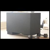
-1 pointsThe Kinetik KCIB12-35 is a sturdily built "intelligent" 12V battery charger with 2/10/20/35 Amp charge rates, alternator voltage check and battery recondition/desulfation functions. It features an easy to read 3-character display, four clearly marked push buttons for on/off and accessing the functions, and 4 LED indicators. It also features a heatsink that covers the majority of the front section, a built in cooling fan and the rear of the unit also functions as a storage compartment for the wires. Recondition According to the literature, as lead acid batteries discharge sulfate can build up on the plates, causing them to not fully accept a charge. Reconditioning (Desulfation) of the battery is accomplished by sending electrical impulses to the battery over a given period of time to break down this build up and allows the battery to better accept a charge and release energy more quickly. This seems to be a useful feature for not only under-hood batteries but also auxiliary batteries that may repeatedly be discharged. Very simple process. Just connect the charger to the battery and press the button! The large teeth and strong springs keep a tight clamp on the terminals. The downside is that this is a long procedure, however there's no way around this as it's simply a long process. The manual states it takes up to 24 hours. When using this mode on an HC1800 I had in the garage it seemed to take around 20 hours.....which while a long time, was shorter than anticipated. Charging The 2/10/20/35 amp charging allows you to select charging rate based on the size of the battery. The 2/10 are of course for smaller batteries, 20 for normal auto batteries, and the 35A rate is for large truck batteries or banks of batteries. It charges in three stages; Rapid Start Charge delivers maximum charging amperage (also allows for quick engine starting in as little as 2 minutes) Absorption Charge maintains the maximum possible charge at a constant voltage Top-off Charge voltage is automatically maintained and reduced to a predetermined level while current is adjusted to a safe battery charge level This process as well as the actual battery charge rate are monitored and adjusted automatically by the microprocessor. After desulfating the battery, I topped it off with a charge using the 20A setting. Again a very simple and surprisingly quick operation. Press the rate selector button until the desired rate of charge is displayed and let it do it's thing. The display will read "FUL" when the battery is fully charged. While I didn't watch it like a hawk, the process took less than a 4 hour interval. The charger appeared to stay nice and cool throughout the entire process. Alternator Check With the car running and charger connected, the manual asks you leave all accessories off and press the Alternator Check button, and then turn all accessories on a perform the same test. If the charger determines that the alternator is okay, the Alternator Good LED lights. Checked it on my car with the stock alt, and both times it indicated my alt was A-OK :thumbup: Overall, I would say this is a great charger. Useful features for the car audio crowd in the desulfator and higher 35A charge for battery banks, convenient storage and carrying handle, all built into a fairly compact case. It's extremely easy to use, stays cool while in use and quick charging times.-1 points
-
-1 pointshttp://www.monsterca...tor_Article.pdf DAMPING FACTOR By Richard Clark At a recent AUTOSOUND 2000 manufacturer sponsored seminar, we were asked to comment on the subject of amplifier damping factor. I was extremely surprised to find how much importance was attached to this single specification. Since most folks are a little unclear as to the true meaning of damping factor, we're presenting the following article. First of all, let's discuss the items that enter into the damping factor calculation. At the heart of this calculation is the output impedance of the amplifier. Most all-modern feedback type amps are of the variety known as constant voltage. This means that they will deliver a constant voltage regardless of their load - at least in theory. Sooner or later the limits of the amplifier's design will prohibit its constant voltage characteristics. It is this constant voltage output characteristic that permits modern car audio amplifiers to deliver more power into a 2 Ohm load than into a 4 Ohm load. A perfect amplifier should be able to double its power every time its output load is halved. Remember, Power = E x E divided by R. As an example, examine the following chart: 8 Ohms = 25 Watts 4 Ohms = 50 Watts 2 Ohms = 100 Watts 1 Ohm = 200 Watts .5 Ohm = 400 Watts .25 Ohm = 800 Watts .0125 Ohm = 1600 Watts If an amplifier were theoretically perfect, then it would be capable of the type of performance described in the chart. However, there are many factors that influence this capability. First there is the power supply section of the amplifier. Even if an amplifier had an unlimited power supply with output transistors that could handle the current, the design would still not be able to achieve the theoretically perfect output. The reason being that we do not have access to theoretically perfect components. Never lose sight of the fact that real components in real amplifiers are subject to real losses. These losses are a result of junction losses; IR drops in connections and losses in resistances and reactance. Losses in the output stages essentially form a voltage divider on the output of the amplifier. This drop is always in series with the load and can be indicated as in Figure N. In the design of an amplifier, the feedback network is usually wrapped around the section with the most losses. These losses can be greatly minimized due to the fact that the feedback node is constantly being corrected. This can be depicted as in Figure O. Output Impedance Determines Damping Factor If the output impedance of an amplifier is extremely low, the effect of loading on the output of the amplifier will be minimal. This means that it will not experience a voltage loss across its own output impedance. This output impedance does more than determine the effect of loading on the amp. It also determines its damping factor. Whenever a signal is fed into a loudspeaker the cone of the speaker will move. Since the cone has mass, there will be mass in motion. Mass in motion means momentum. When the signal is removed from the loudspeaker, the momentum of the cone causes the energy stored in the cone to be fed back into the amplifier. If our perfect amplifier were connected to this speaker, the loudspeaker would be trying to produce a voltage into 0 Ohms. Remember, a perfect amplifier has an output impedance of 0 Ohms which is essentially a short circuit. A voltage cannot be developed across 0 Ohms because it would require an infinite amount of current. It is this same infinite amount of energy that would now be trying to prevent the speaker cone from moving. If such were the case, we would certainly have a "tight" sounding speaker with absolutely no hangover. The good news is that quality amplifiers have very low output impedances. We are very pleased to report that there are many car audio amplifiers on the market with output impedances on the order of .01 Ohms or less! Calculating Damping Factor Let's clarify a few points before starting our calculations. The frequency of the measurement and the impedance of the load need to be specified. For example, the use of a 1 KHz signal and a load impedance of 4 Ohms would be a typical specification. DEFINITION = A good definition of damping factor would the ratio of the output impedance of the amplifier to the impedance of the load specified at a given frequency. An amplifier with an output impedance of 0.5 Ohm will have a damping factor of 8 when connected to a theoretically perfect 4 Ohm loudspeaker (i.e. purely inductive voice coil.) since 4/.5 = 8. The following chart assumes such a 4 Ohm speaker: Output Impedance Damping Factor 4 Ohms 1 2 Ohms 2 1 Ohm 4 .5 Ohm 8 .25 Ohm 16 .125 Ohm 32 .062 Ohm 64 .031 Ohm 128 .0015 Ohm 256 .0007 Ohm 512 .0003 Ohm 1024 .00015 Ohm 2048 .00007 Ohm 4096 .00003 Ohm 8192 Now, for the bad news; it is easy to see how a race to produce such a high damping factor led to a specification so often quoted by salespeople. The numbers on modern amplifiers (with lots of feedback) can get very large and they are easy to compare. Sometimes we can get caught up in these big numbers and we totally miss the point. Effective Damping Factor (EDF) In the case of damping factor, I believe that it could be compared to the old saying of not being able to see the forest because of all the trees. The only thing that really matters is Effective Damping Factor (EDF). Effective Damping Factor more accurately describes the interaction between a real amplifier and a real speaker. Unfortunately real speakers have a real problem with EDF. This is due primarily to the DC resistance of the voice coil. When we calculate the EDF of an amplifier and speaker, it is absolutely necessary that we include this DC resistance into the formula. Figure P illustrates the inclusion of the speaker's impedance into the EDF. The actual impedance of the speaker may be 4 Ohms. If we measure the voice coil of this speaker, we will probably find that it has a DC resistance of about 3 Ohms. When calculating the EDF effect on this speaker, we must add the 3 Ohms of DC resistance as if it were a resistor between the output of the amp and the voice coil of the speaker. Remember the resistive part of the speaker is the part where the signal is turned into heat. No work is actually done in this resistance. The inductive element of the voice coil is the only part that does work to create sound. This is one reason speakers are so inefficient. Most of the voice coil is a resistive element that can do no work. Someday if we develop room temperature superconductors and can afford to use them for voice coils, we are going to see some really efficient speakers. From the damping factor chart it is obvious that the most damping we can expect from our amp/speaker combination is only about two. An amplifier with a damping factor exceeding 10 times this amount is no longer going to play a significant role in this overall calculation. This would yield a practical limit on amplifier damping requirements to about twenty. There are times when the actual damping factor can exceed this number; one such case would be that of a dynamic loudspeaker in resonance. As we have learned, at resonance a loudspeaker's impedance is at a maximum level. At resonance, the DC element stays the same and only the reactance increases. This means that the ratio gets larger and the DC element becomes a smaller percentage of the total. For example, if the speaker impedance at resonance increased to 40 Ohms and the DC resistance was still 3 Ohms and the amplifier were .1 Ohms, and then the actual damping could be 40/3.1, or 13. This is certainly much better than 2, but quite a bit short of the 100, 200, or 500 claimed by salesmen who unknowingly think this factor so important. Fortunately for most loudspeakers this extra damping happens where they need it the most. This is because at resonance, speakers typically are very uncontrolled and have the least mechanical damping. It is also this factor that enables us to be able to connect speakers in series and not have to worry about losing damping. The actual impedance of the loudspeakers in series is doubled, but the ratio to the amplifier must also be increased by a factor of 2 to 1. The result is no change in performance. It is quite possible that this information may be in stark contrast to current marketing trends. However this does not change the fact that this information is accurate. The best way to achieve total control over speaker movement is with a servo system. Only armed with a quality servo system can effective damping characteristics be achieved. A servo essentially puts the loudspeaker in the corrective feedback loop of the amplifier. This topic will be the subject of a future article.-1 points