Leaderboard


Popular Content
Showing content with the highest reputation on 03/03/2011 in all areas
-
1 pointVehicle: 1996 GMC JIMMY 4 door 4x4 sittin on 10's( I keep em clean though) Alternator: Iraggi 356 amp MONO Amplifier: Stetsom 5k2d 2 ohms pushing 6850rms H/U: Alpine 117 Front stage: Front doors Polk audio DB 6.5" with Polk audio 4x6 in the dash Rear doors Crescendo super tweeters Multi Channel amplifier: MB QUART 100.4 Batteries: 3 D3400( 1 under the hood and 2 in the back!) Deadener: Spectrum Sludge (3 layers) Power wire: 3 runs of monster cable 1/0 for power (2 directly from alternator and 1 connecting batteries) Ground wire: 6 runs of monster cable 1/0 for ground (1 ground connecting batteries and then 5 grounds directly to chasis less than 3ft a piece) SUBWOOFER box: 18 cubes tuned to 34hz with 220sq inches of port area! SUBWOOFER:2 18" ZCONS Straight BEASTS!
-
1 pointSoo... here's some picof the new hsk 165 Hertz components. And pics of my blown Bravox carbon fiber woofers. (Which I have a question about) Soo... first ar the new hertz comps And now for my question... what is the brownish stuff? It looks kinda like glue that came undone. But idk... but I do kno that it doesn't work... Thanks guys
-
1 point
-
1 pointPower wire fot connecting Batts! 8 gauge speakerwire! All wires are from Monster Cable my STOCKPILE for when I go to war!
-
1 point
-
1 pointMade the other plate for the side. Also tied the plate into the tubing where possible for more strength. Polished the edge of the balljoint sleeve where the plates came together.
-
1 pointWe are pulling out the HU and the EQ. Here is a pic of what's coming out...Both items were not very good quality and it shows. By sefugi at 2011-02-25 This is what was delivered today, hoping to get it installed tomorrow. By sefugi at 2011-02-25
-
1 point^ here... i uploaded to YT. enjoy.
-
1 pointNo truss on the axle. Using semi float stock style 9" axles from Dutchman. They only case harden their axles which gives them more strength without making them brittle. I've bent 1 5/8x1/4" wall with my JD2 but it required an extra long handle for leverage. I have changed my mind on doing the tubular arms anyways though so I won't need to use the bender on this. Got started on a lower A arm today. The coil pocket has been relocated for better alignment with the cylinder and the pocket has been dropped 1" also. I used some 1 1/2x1 1/2x3/16" and some 1x3x1/8" to make a skeleton to hold everything in it's place and add strength. Made sure all the pieces were coped for a tight fit and strong weld. I'm using 1/4" plate for the side plates. The coil bucket will get trimmed down after I cap the top. The tube is welded to the joint sleeve and then the plate is welded to the sleeve on the outside and tied into the tubing also for maximum strength.
-
1 pointHere we go fellas, part two, The final assembly of the battery rack. Here I'm prepping the center rails putting some 9/16" holes at the ends. A little story about this drill press. Pops got it for free from a shop he used to work at. It sat in the garage for 20 years unused. Pops said it needed a new motor, he let me have it. Just for laughs I plugged it in. Snap, it works. Let Pops know, now he needs a drill press. Here I'm laying out the carriage bolt pad centers. I did two angle irons at a time to make sure they line up properly. Here is a close-up so you can see my alignment marks. I also put an indicator at the end of the angle iron to make sure I don't mix them up. This is the center section tack welded together. Here I am laying out the alignment marks for the center section on the battery base. To keep things simple I added up my measurements to I can use a ruler and mark everything in one shot. The finished frames ready to be welded. A couple test fit shots.
-
1 pointReal life progress, yay. I continued work on the battery rack again today. I made the carriage bolt pads. I started off with 4" x 2", 1/8" thick steel strip. I will be putting a square hole in the center of this piece. Here's how I did it. The workpiece, trimmed and ready for drilling. I used work's bada$$ Bridgeport Mill and vise setup to put a 1/4" pilot hole first I followed that up with a 1/2" drill Here I verified the size of the square on the carriage bolt. Get your 3-D glasses on. Here I scribed out the square that I'll cut out. Just wait till you get a load of how I pull this off. That's right, an effing jigsaw. Dios mio! (My goodness!) What a hack job. Not to worry I can fix it. A little file action, and presto change-o, square hole. Test fit. Finished product. Stay tuned for part two of this update.
-
1 pointThis picture marks where the 29.5 inch mark is from my last box (How tight it was hahaha) And this is what my old box looked like Assuming your roof is the same height as mine, you might have some problems with the subs facing the roof... same with the depth being 38" and being that tall..... if youre taking your rear seats out, then the only problem would still be the subs too close to the roof being only 2 inches or so away. I think perhaps you may want to look into your dimensions again just in case (prove me wrong please )
-
1 point
-
1 pointSmall signs of progress. I updated the battery rack CAD a bit. I think this is going to work better than what I had before. Here is a shot from the top. I added the battery hold downs, and detailed the whole assembly with some hardware. From the bottom looking up. Here is a shot of the hanger from the bottom up. You can see some of the hardware I'll be using. One last one of the hanger from the top down. Now some progress in the real world. This one is me testing the strength of the angle irons that I'll be using. My cutting rig. The rack coming together. This is how I handled the corners. I tacked them together, I'll have a friend with a bigger welder finish them off. Plus he's a better welder than me. o_o
-
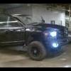
1 pointThanks fellas,,, Heres the latest pic's of The Diesel Finally got the paint done..... No more chrome on this bad boy.. A little dirty but you get the idea.. Putting LED's in the box... And a shot loaded with the sledge hammers.....
-
1 pointPics of 140 amp HO Alt and final 1/3 of Big 3 installed. Also replaced both belts while I had them off.
-
1 pointAnd vids:
-
1 pointSub and box are going in my bro-in-law's build, just borrowing them until my box and sub are done. Sub is running 8 ohms of my AP18001D for ~300-350 rms and it bangs!
-
1 pointAight, for those of you who hung in there, this is where it starts to pay off, lol. Got my hands on a camera finally. Here it goes...
-
1 pointHey everybody! Not much got done in the real world today, but tons got done virtually. Hmm, that second part didn't come out quite right..... Any who, here is a little CAD action, and I ain't talking about cardboard and duct tape here. Here is a 3-D CAD model of a deka 9a31 Frame rails. Really! Here we go. Starting to make sense? Battery tray anyone? Tangerine supports? WTF? The semi-complete assembly. How about some batteries to complete the picture. A look from the bottom up. Chime in now or forever hold your piece.
-
1 pointWhat's up everybody? Not much here, just got some work done on the box. With regards to tools, I got what I got and that's that. Working solo it's a pain trying to manage a full sheet of MDF on a wienie tablesaw. As it happens the cargo area of my Suburban measures 49" wide. Sheets of MDF in this area come in a 49" width. I had my box designed to a 49" width. This way I had the guys at the local Home Depot cross cut the sheet to the length I needed with their fancy panel saw. The guys were pretty cool about cutting the wood for me after I told them what I was doing. They thought I was nuts though. I used my table saw for the finish cuts and all the angle cuts. Here are some pics of what I got. I opted to paint the inside of the box plain ass boring grey. I have no creativity. I used some threaded inserts as a foundation to run some bolts through the wood for wiring. Here is the wires I ran through the port. Double runs of 8 gauge wire, because I can. So far so good, more on the way.
-
1 pointI got my screens in. The alpine NAV-1 is okay. To be honest I'm not too impressed with the graphical interface. My wife has a Pioneer 920Bt in her car, I like it better. Oh well, what is nice is that I can play a movie to the rear screens and listen to the radio at the same time. That way the little ones can enjoy a flick through headphones while I keep my sanity through music on long road trips. I used "The Black Box BB-R3" bypass from buysellauction on ebay. It was cheap and USA made so I figured what the heck. It works and I couldn't be happier. Any ways, here are some pics. Here is a close up of the Alpine NAV-1
-
1 pointHahaha. I hope soon, but I've got a ways to go. I've got to figure out how to mount my babies, I mean batteries. Here is a pics of their arrival home.
-
1 pointHere are a few pics of how I got the components into the q-logic panels. I didn't have a 4"+ hole saw, so I improvised. I used a smaller saw to cut out the center. I sketched out the profile of the hole I needed to cut, then I scored the plastic with a blade. I used to some pliers to break off the scored pieces of plastic leaving me with a semi-nice large diameter hole. I decided to make a backing ring to secure the mid to the panel. Here is the ring I cut at work using a CNC plasma cutter. I am using rivnut style inserts to mount the driver. Here is the installed product. More on the way.
-
1 pointLatest pics..... Box pics.... Our Logo in the box...


